
Industrial Memory & Storage
Browse memory and storage for current and legacy industrial platforms by generation, interface and form factor. Confirm the final configuration against your platform, operating conditions and planned project lifecycle.
Industrial Memory
U‑DIMM and SO‑DIMM configurations for DDR3, DDR4 and DDR5 industrial platforms. Selection is determined by the target memory architecture, board layout and program lifecycle.
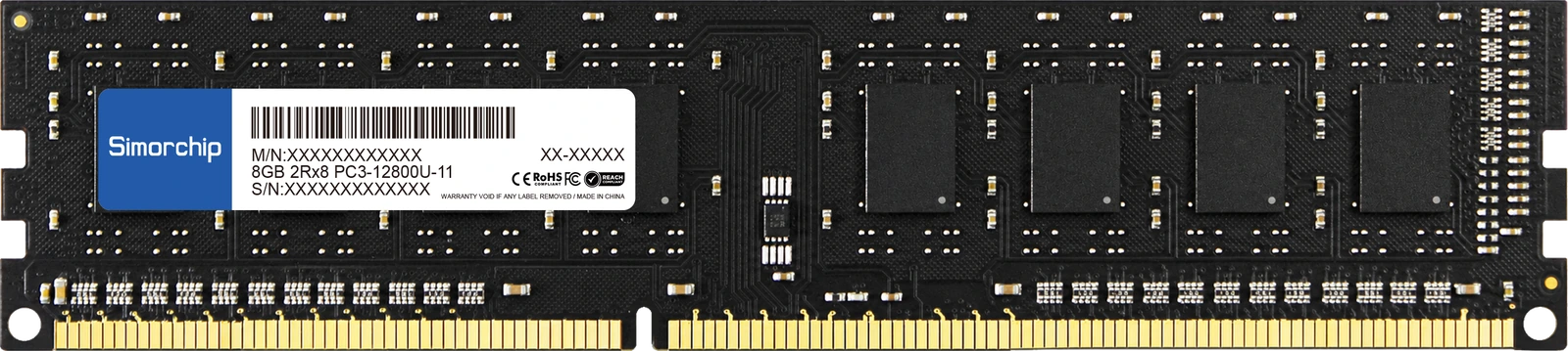
DDR3 U‑DIMM
For platforms using the 240‑pin DDR3 / DDR3L U‑DIMM memory architecture.
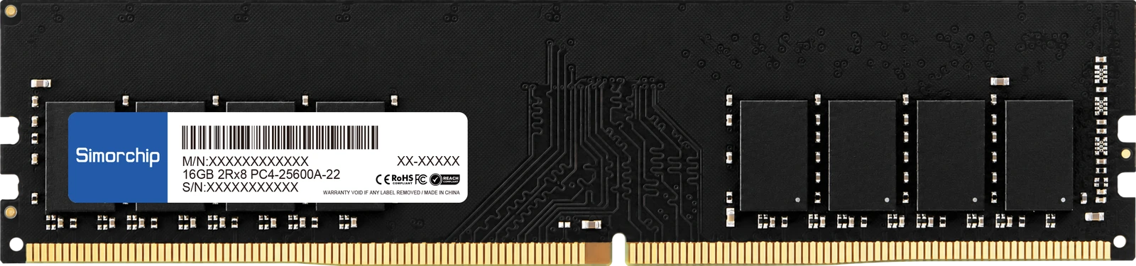
DDR4 U‑DIMM
For platforms using the 288‑pin DDR4 U‑DIMM memory architecture.
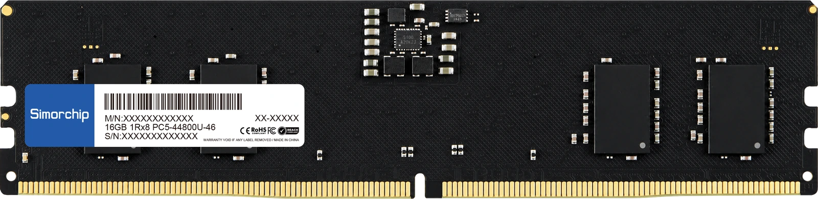
DDR5 U‑DIMM
For platforms using the 288‑pin DDR5 U‑DIMM memory architecture.
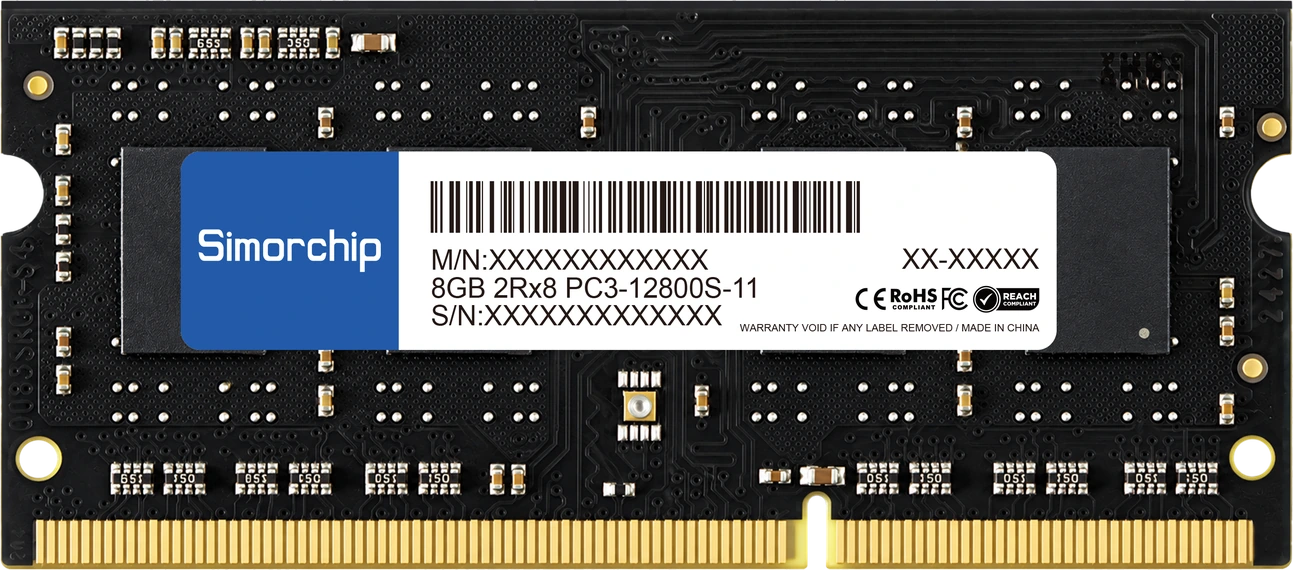
DDR3 SO‑DIMM
For platforms using the 204‑pin DDR3 / DDR3L SO‑DIMM memory architecture.
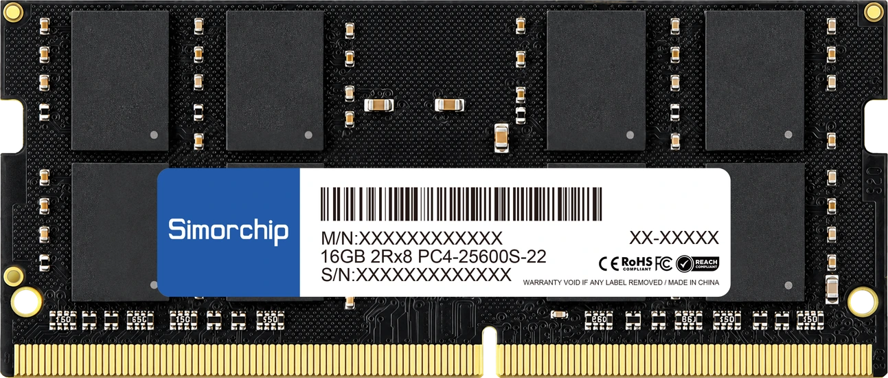
DDR4 SO‑DIMM
For platforms using the 260‑pin DDR4 SO‑DIMM memory architecture.
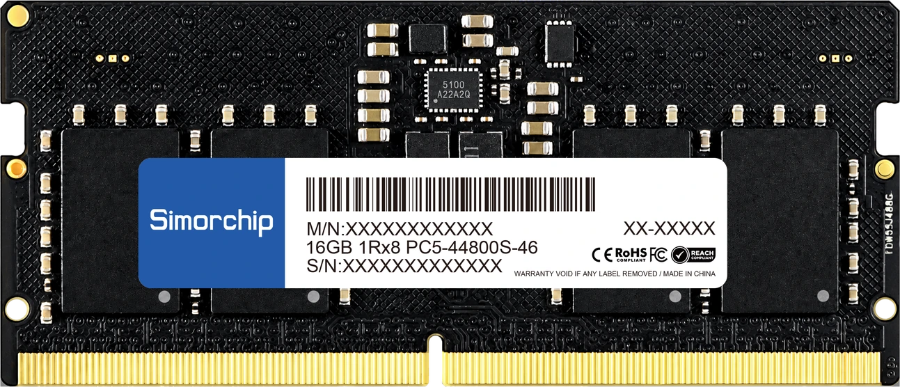
DDR5 SO‑DIMM
For platforms using the 262‑pin DDR5 SO‑DIMM memory architecture.
Industrial Storage
SATA and PCIe storage products organized by interface and physical form factor for industrial platform integration.
Form Factor Reference
Relative physical dimensions of storage form factors represented in the current industrial portfolio.
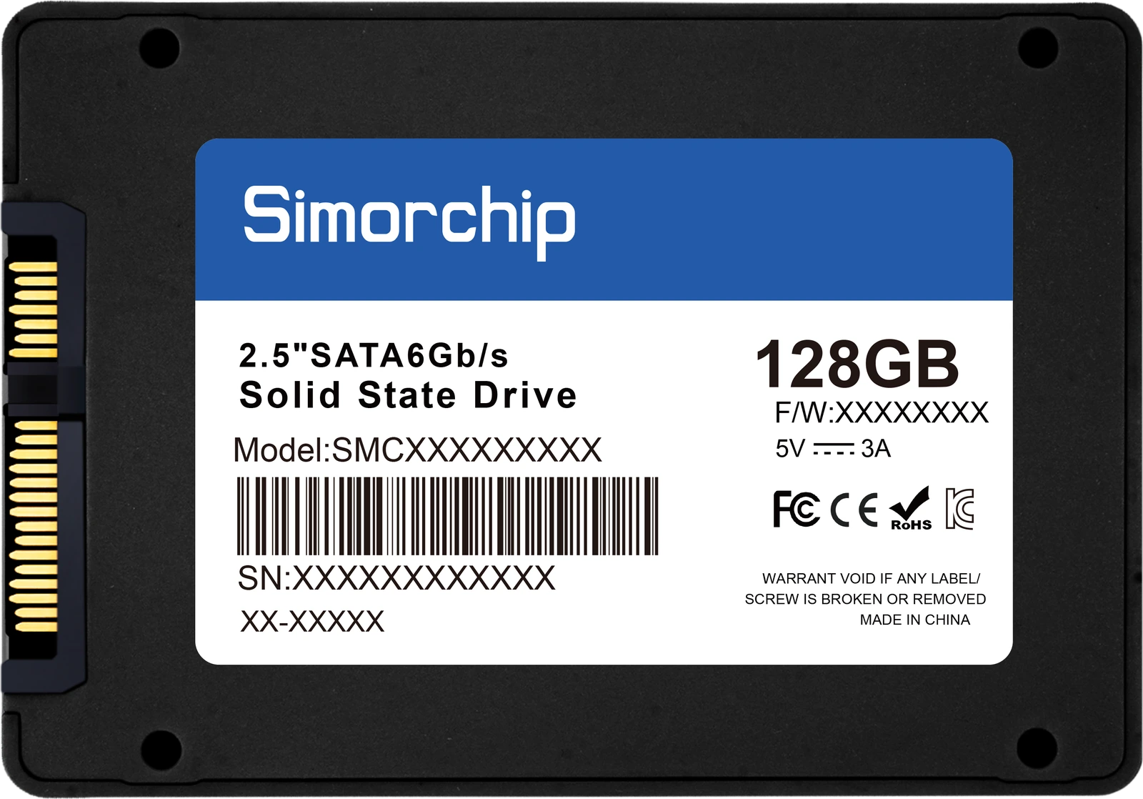
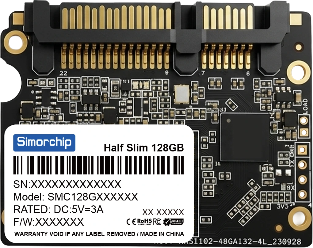
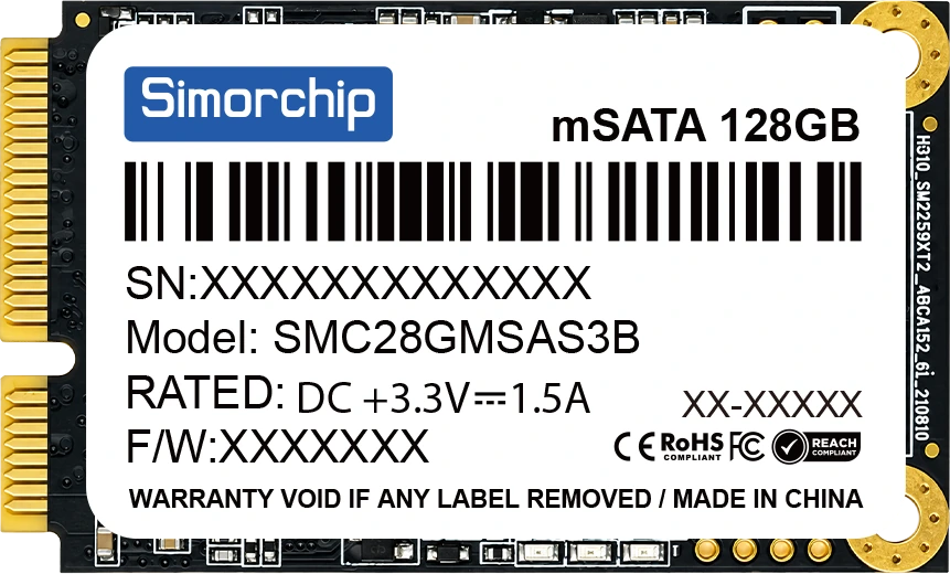
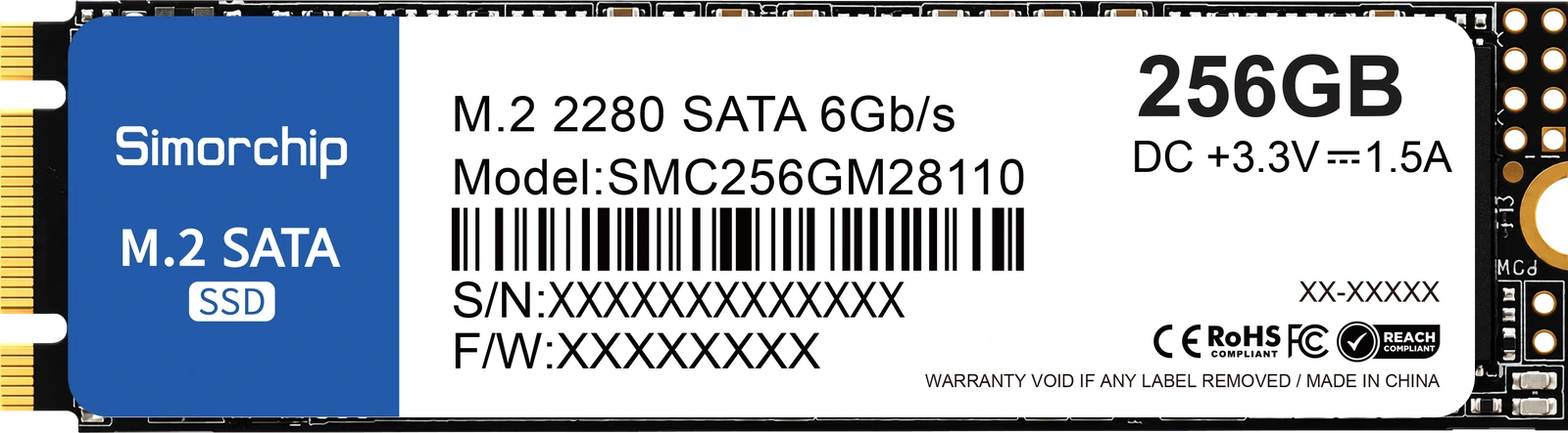
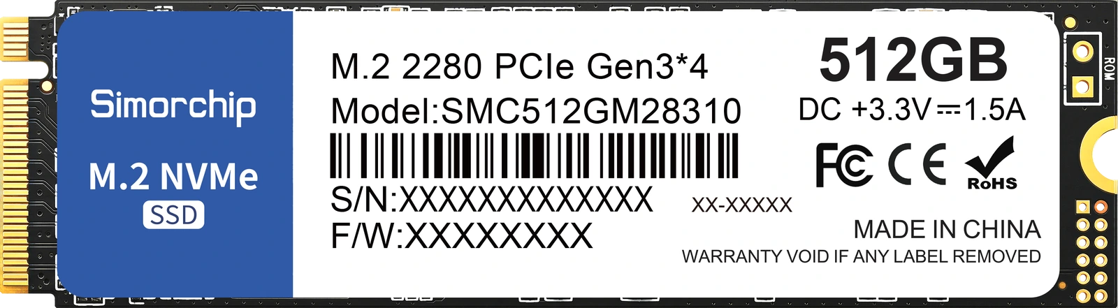
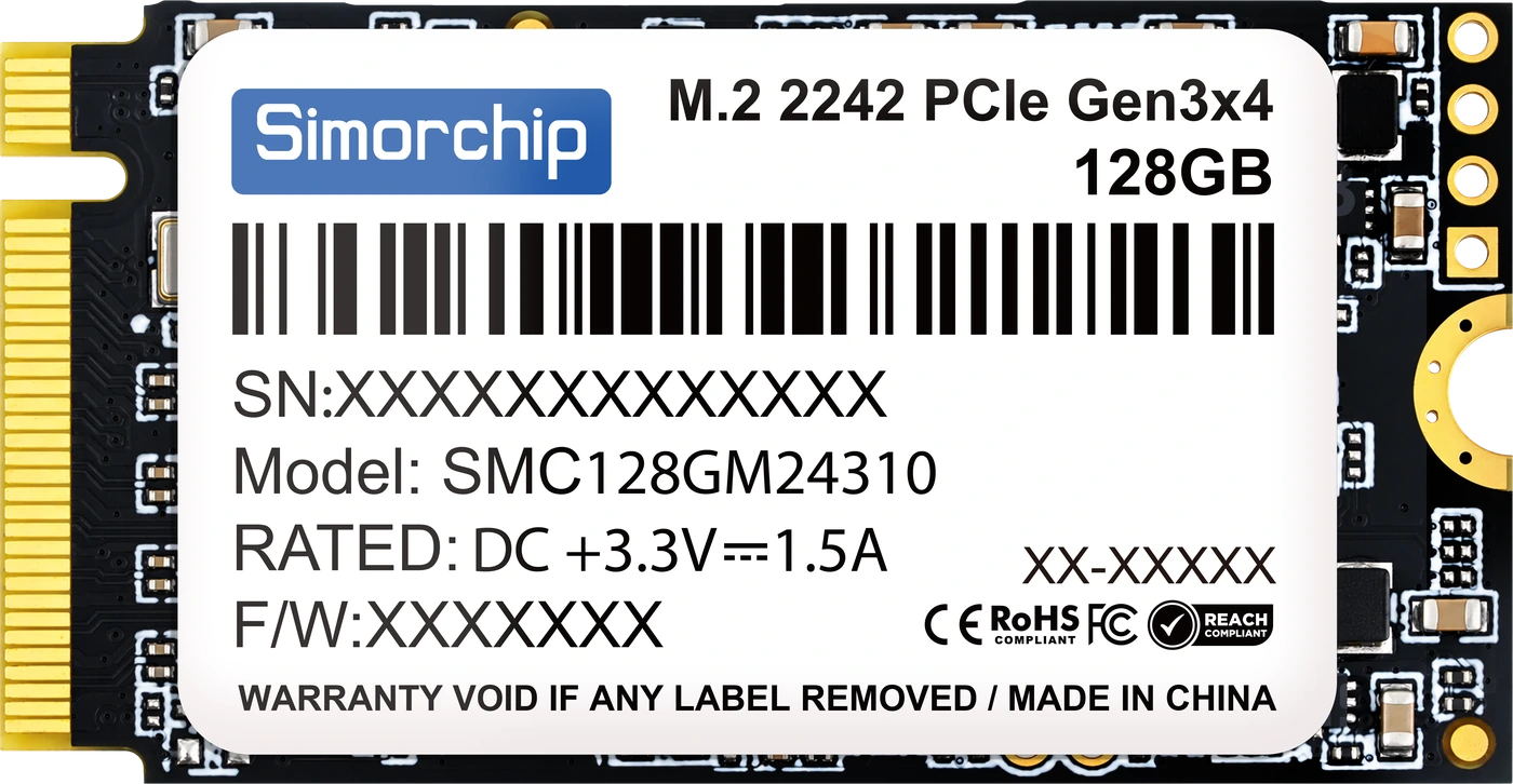
Shown to relative scale. Dimensions are the form-factor footprint, not the drive height.
SATA
2.5″ SATA III
2.5‑inch SATA drive for systems with a standard 2.5‑inch drive bay.
mSATA
mSATA module for boards with an mSATA socket.
Half Slim
Half Slim SATA module for space-constrained board layouts.
M.2 2280 SATA III
M.2 2280 module operating on the SATA interface, not PCIe.
PCIe / NVMe
M.2 2242 PCIe Gen3 x4
M.2 2242 module on PCIe Gen3 x4 with NVMe 1.4 protocol support.
M.2 2280 PCIe Gen3 x4
M.2 2280 module on PCIe Gen3 x4 with NVMe 1.4 protocol support.
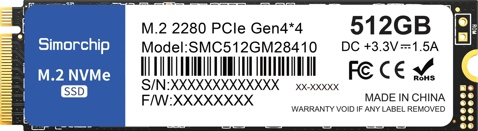
M.2 PCIe 4.0
M.2 module on PCIe Gen4 x4 with NVMe protocol support.
Specifications provided on request.
Submit Product Requirements →Performance figures represent the maximum values for each product family and vary by capacity. Refer to each datasheet for performance specifications by capacity. M.2 is a form factor, not an interface: the SATA and PCIe M.2 families are separate products.
Program Controls
Configuration Control
If configuration control is included in the agreed project scope, qualified configurations follow the agreed BOM and change-review requirements.
Platform Qualification
Applicable memory and storage products may be evaluated against the target platform configuration according to project requirements.
Lifecycle Coordination
Component availability, generation transitions and requalification requirements are reviewed against the expected program period.
Product Configuration Review
Provide the target platform, required memory or storage form factor, capacity requirements, operating conditions and expected program lifecycle. SIMORCHIP engineering will review the applicable product configuration and qualification scope.